ブランド
おすすめ商品
-
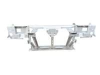 TM WORKS 180SX/240SX/S13系シルビア オリジナルコアサポートキット
165,000円(税15,000円)
-
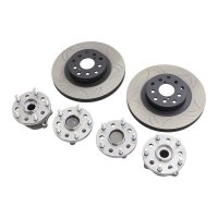 GKTech 86 / BRZ / GR86 5X114.3 フロント変換ハブ
SOLD OUT
-
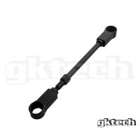 GKTech 日産 180SX ヘッドライト モーター リンク ロッド アセンブリ
5,899円(税536円)
-
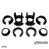 GKTech Z33 350Z/V35 リアサブフレームスリップインカラー
SOLD OUT
-
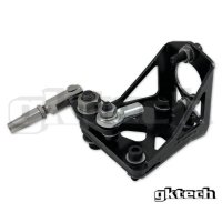 GKTech 純正レバー 油圧ブレーキ化マウントキット
15,399円(税1,400円)
-
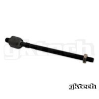 GKTech 86 / GR86 / BRZ スーパーロック交換用インナータイロッド - 単品販売
5,500円(税500円)
-
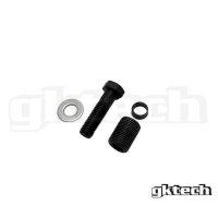 GKTech S13/S14/S15 ナックルアダプター補修・変換部品(タイロッド側)
1,430円(税130円)
-
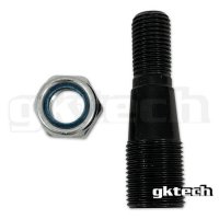 GKTech S14/S15 ナックルアダプター補修部品(ロアアーム側)
2,042円(税186円)
-
 BBS-RS/LM対応 アウターリム 15~19インチ
28,600円(税2,600円)
-
 OZ フッツーラ・ペガソ対応 アウターリム 17~19インチ
31,680円(税2,880円)
-
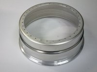 BBS-RS/LM対応 インナーリム 15~19インチ
34,760円(税3,160円)
-
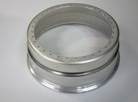 OZ フッツーラ・ペガソ対応 インナーリム 17~19インチ
36,740円(税3,340円)
-
 NISSAN SR20 上置き マニホールド S13/S14/S15
186,000円(税16,909円)
-
 GKTech Z33/V35 V2スーパーロックロアアーム 350Z/フェアレディZ
SOLD OUT
-
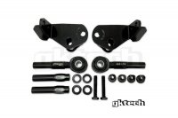 GKTech V3 Z33 350z/V35 ステアリング アングル キット
SOLD OUT
-
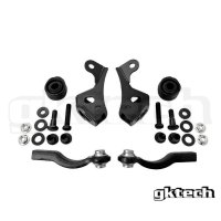 GKTech V3 86/GR86/ZC6 BRZ ボルトオンアングルキット(アッカーマン調整可)
47,300円(税4,300円)
-
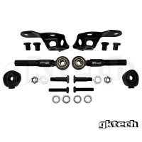 GKTech Z34 370Z/V36 スーパーロック アングル キット
SOLD OUT
-
 GKTech/STRIKE FAST - Z33 350Z/V35 ショートシフター
86,072円(税7,825円)
-
 GKTech/STRIKE FAST - 86/GR86/BRZ ショートシフター
70,950円(税6,450円)
-
 PowerTune Digital GPS Dash/デジタルダッシュディスプレイGPS付
95,200円(税8,655円)
-
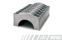 RAD Industries 2JZ-GE 2JZ-GTE 1JZ-GTE ビレットメインキャップ
103,480円(税9,407円)
-
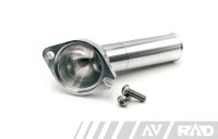 RAD Industries 2JZ-GTE ビレットロアウォーターネック
48,125円(税4,375円)
-
 RAD Industries 2JZ-GTE ビレットタイミングベルトテンショナーブラケット
42,735円(税3,885円)
-
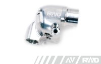 RAD Industries 2JZ-GTE ビレットアッパーウォーターネック
63,525円(税5,775円)
-
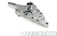 RAD Industries 2JZ-GTE ビレットウォーターインレット オルターネーターブラケット
71,745円(税6,522円)
-
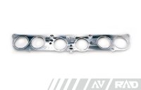 RAD Industries 2JZ-GE ビレットGTEサージタンク変換アダプター
45,932円(税4,176円)
-
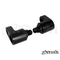 GKTech 86/GR86/BRZ ステアリングラックオフセットアダプター
15,730円(税1,430円)
-
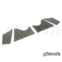 GKTech 86/GR86/BRZ フロントメンバー クリアランス増溶接プレート
6,050円(税550円)
-
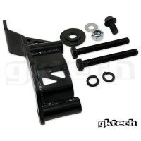 GKTech Z34 370Z デフブレース
SOLD OUT
-
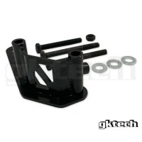 GKTech Z33 350Z / V35デフブレース
13,420円(税1,220円)
-
 TOYOTA 1JZ 上置き マニホールド VVTi有 JZX100
228,800円(税20,800円)
-
 GKTech S13/180SX/S14/S15 油圧ハンドブレーキマウント(汎用タイプ)
4,620円(税420円)
-
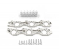 FRANKLIN ENGINEERING 1JZ/2JZ VR38 コイルブラケットセット
64,900円(税5,900円)
-
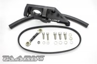 TAARKS パワステポンプ移動ブラケット S14/S15
26,400円(税2,400円)
もっと見る
-
 TM WORKS 180SX/240SX/S13系シルビア オリジナルコアサポートキット
165,000円(税15,000円)
-
 GKTech 86 / BRZ / GR86 5X114.3 フロント変換ハブ
SOLD OUT
-
 GKTech 日産 180SX ヘッドライト モーター リンク ロッド アセンブリ
5,899円(税536円)
-
 GKTech Z33 350Z/V35 リアサブフレームスリップインカラー
SOLD OUT
-
 GKTech 純正レバー 油圧ブレーキ化マウントキット
15,399円(税1,400円)
-
 GKTech 86 / GR86 / BRZ スーパーロック交換用インナータイロッド - 単品販売
5,500円(税500円)
-
 GKTech S13/S14/S15 ナックルアダプター補修・変換部品(タイロッド側)
1,430円(税130円)
-
 GKTech S14/S15 ナックルアダプター補修部品(ロアアーム側)
2,042円(税186円)
-
 BBS-RS/LM対応 アウターリム 15~19インチ
28,600円(税2,600円)
-
 OZ フッツーラ・ペガソ対応 アウターリム 17~19インチ
31,680円(税2,880円)
返品について
- 返品期限
- 初期不良以外のお客様都合での返品はお受けできませんが商品発送前(在庫品)であればキャンセル対応が可能です
商品は予告なくメーカーによる仕様変更を行う場合がございます。それらについては交換や返品の対象にはなりません - 返品送料
- 初期不良発生時の送料は当社が負担致します
初期不良以外の保証対応につきましてはお客様送料負担となります - 不良品
- 保証期間を明記していない商品に関しては初期不良のみの対応となります
初期不良/商品間違い/部品欠品などは商品到着後5日以内にご連絡下さい
なお使用後の商品、改造などをされている場合にはお受けできない場合もございます
不良発生時における工賃、その他費用は一切、保証致しません
輸入商品に関しての注意事項として性能に支障のない範囲で外箱の損傷や傷などがある場合がございます
動作、使用に影響のある場合には交換対応をいたしますが、それら意外においては対応できかねますため事前に了承のうえご注文をお願いします
メーカー保証のある製品に関してはメーカー判断のもと保証対応が認められた場合にのみ適用されます。
保証が認められた場合にも修理、交換商品にかかる送料(国際送料)はそれに含まれません。
配送・送料について
- 佐川急便
-
通常商品は一律1300円で発送致します。
ホイール部品(リム)は個別送料での計算です。
※沖縄、離島に関しては送料着払いでの発送になります。(表示は0円となります)
支払い方法について
- PayPay銀行(銀行振込)
- PayPay銀行からの同行間の送金は振込手数料50円(税別)で24時間対応しております。
- クレジットカード決済
-


対応:VISA・MASTER・DINERS・JCB・AMEX
※リボ・複数回払いは利用できません - PayPay(ペイペイ)
- 「PayPay」アカウントがあれば、商品代金をかんたん・スムーズにお支払いができる決済サービスです。オンライン決済ではPayPay(残高)、PayPay(クレジット)※旧あと払い でのお支払いが可能です。
- Amazon Pay
- 「Amazon Pay」は、Amazon.co.jpアカウントに登録された住所情報とお支払い情報を使って、商品やサービスの支払いができるサービスです。
- PayPal(ペイパル)
- ご注文手続きでPaypalの支払い画面へ移動します。「ペイパルとは?」ペイパルは、インターネット上の便利な【デジタルおさいふ】です。ペイパルにクレジットカード情報を登録しておけば、IDとパスワードだけで決済完了。お店に大切なカード情報を知らせることなく、より安全に支払いができます。ペイパルアカウントの開設は、決済方法でPayPalを選択して必要事項を入力するだけなのでかんたんです。
営業日について
| 日 | 月 | 火 | 水 | 木 | 金 | 土 |
|---|---|---|---|---|---|---|
| 1 | 2 | 3 | 4 | 5 | ||
| 6 | 7 | 8 | 9 | 10 | 11 | 12 |
| 13 | 14 | 15 | 16 | 17 | 18 | 19 |
| 20 | 21 | 22 | 23 | 24 | 25 | 26 |
| 27 | 28 | 29 | 30 |
| 日 | 月 | 火 | 水 | 木 | 金 | 土 |
|---|---|---|---|---|---|---|
| 1 | 2 | 3 | ||||
| 4 | 5 | 6 | 7 | 8 | 9 | 10 |
| 11 | 12 | 13 | 14 | 15 | 16 | 17 |
| 18 | 19 | 20 | 21 | 22 | 23 | 24 |
| 25 | 26 | 27 | 28 | 29 | 30 | 31 |
